
Product Detail
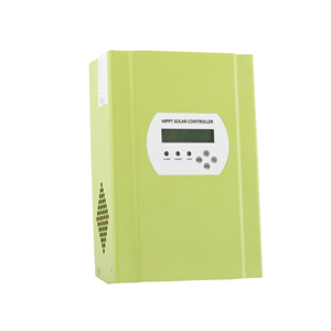
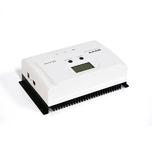
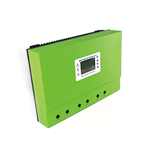
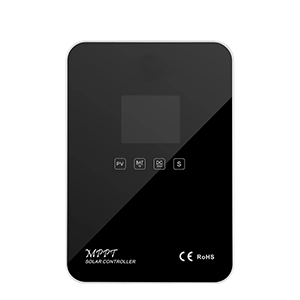
2. Following are the parameter of MPPT Solar Charge Controller 60A.
|
LEYU OPM -40A/50A/60A -series |
40A |
50A |
60A |
|||||
|
Charge Mode |
Maximum Power Point Tracking |
|||||||
|
Method |
3 stages: fast charge(MPPT),constant voltage, floating charge |
|||||||
|
System Type |
DC12V/24V/48V |
Automatic recognition |
||||||
|
System Voltage |
12V system |
DC9V~DC15V |
||||||
|
24V system |
DC18V~DC30V |
|||||||
|
48Vsystem |
DC36V~DC60V |
|||||||
|
Soft Start Time |
12V/24V/48Vsystem |
≤10S |
||||||
|
Dynamic Response Recovery Time |
12V/24V/48Vsystem |
500us |
||||||
|
Conversion Efficiency |
12V/24V/48Vsystem |
≥96.5%,≤99% |
||||||
|
PV Modules Utilization Rate |
12V/24V/48Vsystem |
≥99% |
||||||
|
Input Characteristics |
||||||||
|
MPPT Working Voltage and Range |
12V system |
DC18V~DC150V |
||||||
|
24V system |
DC34~DC150V |
|||||||
|
48V system |
DC65~DC150V |
|||||||
|
Low Voltage Input Protection Point |
12V system |
DC16V |
||||||
|
24V system |
DC30V |
|||||||
|
48V system |
DC60V |
|||||||
|
Low Voltage Input Recovery Point
|
12V system |
DC22V |
||||||
|
24V system |
DC34V |
|||||||
|
48V system |
DC65V |
|||||||
|
Max DC Voltage |
12V/24V/48V system |
DC160V |
||||||
|
Input Overvoltage Protection Point |
12V/24V/48V system |
DC150 |
||||||
|
Input Overvoltage Recovery Point |
12V/24V/48V system |
DC145V |
||||||
|
Max. PV Power |
12V system |
570W |
700W |
900W |
||||
|
24V system |
1130W |
1400W |
1700W |
|||||
|
48V system |
2270W |
2800W |
3400W |
|||||
|
Output Characteristics |
||||||||
|
Selectable Battery Types (Default type is GEL battery) |
12V/24V/48Vsystem |
Sealed lead acid,
vented, Gel, NiCd battery |
||||||
|
Constant Voltage |
12V/24V/48V system |
Please check the charge voltage according to the battery type form. |
||||||
|
Floating Charge Voltage |
12V/24V/48V system |
|||||||
|
Over Charge Protection Voltage |
12V system |
14.6V |
||||||
|
24V system |
29.2V |
|||||||
|
48V system |
58.4V |
|||||||
|
Rated Output Current |
12V/24V/48V system |
40A |
50A |
60A |
||||
|
Current-limiting Protection |
12V/24V/48V system |
44A |
55A |
66A |
||||
|
Rate charge current |
12V/24V/48V System |
40A |
50A |
60A |
||||
|
Temperature Factor |
12V/24V/48V system |
±0.02%/℃ |
||||||
|
Temperature Compensation |
12V/24V/48V system |
14.2V-(The highest temperature-25℃)*0.3 |
||||||
|
Output Ripples(peak) |
12V/24V/48V system |
200mV |
||||||
|
Output Voltage Stability Precision |
12V/24V/48V system |
≤±1.5% |
||||||
|
Charge voltage Peak-Peak Ripple |
12V/24V/48V System |
200mV |
||||||
|
Charger voltage accuracy |
12V/24V/48V System |
≤±1.5% |
||||||
|
Discharge characteristic |
||||||||
|
Setting Control |
Controller or LAN |
|||||||
|
Max discharge current |
12V/24V/48V System |
40A |
||||||
|
Discharge protection |
12V/24V/48V System |
fuse 30A*2 |
||||||
|
Double-time control |
12V/24V/48V System |
On in morning ,off in morning / On in night ,off in night |
||||||
|
ON / OFF mode |
12V/24V/48V System |
ON / OFF |
||||||
|
PV voltage control |
12V/24V/48V System |
PV voltage on,PV voltage off |
||||||
|
PV voltage / time delay control |
12V/24V/48V System |
PV voltage on,time delay off |
||||||
|
Discharge voltage protection |
12V/24V/48V System |
Output off when it under setting voltage; Factory set is 10.5 .( Note : set based on 1 battery ) |
||||||
|
Communication Features |
||||||||
|
RS232 Communication |
12V/24V/48V System |
Chose COM communication |
||||||
|
LAN Communication |
12V/24V/48V System |
Set IP and Gate address for controller and solar eagle ;Then chose TCP communication |
||||||
|
Protection |
||||||||
|
Input Low Voltage Protection |
Check the input characteristics |
|||||||
|
Input Overvoltage Protection |
Check the input characteristics |
|||||||
|
Input Polarity Reversal Protection |
yes |
|||||||
|
Output Overvoltage Protection |
Check the output characteristics |
|||||||
|
Output Polarity Reversal Protection |
yes |
|||||||
|
Short-circuit Protection |
Recover after eliminating the Short-circuit fault, no problem for long term Short-circuit |
|||||||
|
Temperature Protection |
95℃ |
|||||||
|
Temperature protection |
Above 85℃,decrease the output power, decrease 3A per degree. |
|||||||
|
Other Parameters |
||||||||
|
Noise |
≤40dB |
|||||||
|
Thermal methods |
Forced air cooling, fan speed rate regulated by temperature, when inner temperature is too low, fan ran slowly or stop; when controller stop working, fan also stop ran. |
|||||||
|
Components |
World brand raw materials. Compliance with EU standards. All rated temperature of electrolytic capacitors not less than 105℃ |
|||||||
|
Smell |
No peculiar smell and toxic substances. |
|||||||
|
Environment Protection |
Meet the 2002/95/EC,no cadmium hydride and fluoride |
|||||||
|
Physical |
||||||||
|
Measurement DxWxH (mm) |
270*185*90 |
|||||||
|
N.G(kg) |
3 |
|||||||
|
G.N(kg) |
3.6 |
|||||||
|
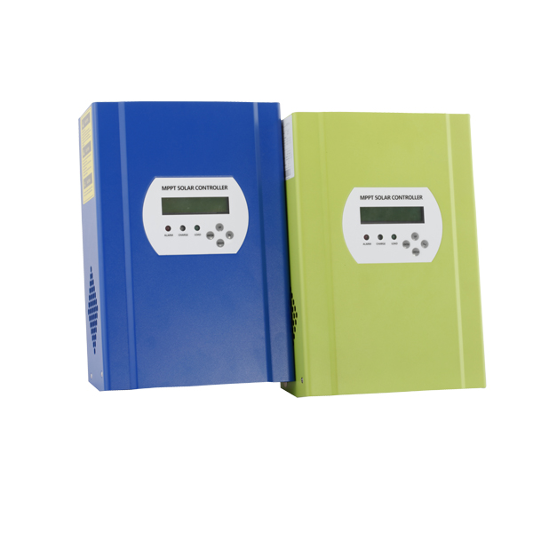
Color |
Blue/Green (optional) |
|||||||
|
Safety |
CE, RoHS, PSE,FCC |
|||||||
|
EMC |
EN61000 |
|||||||
|
Type of Mechanical Protection |
IP21 |
|||||||
|
Environment |
||||||||
|
Humidity |
0~90%RH ( no condense) |
|||||||
|
Altitude |
0~3000m |
|||||||
|
Operating Temperature |
-20℃ ~ +40℃ |
|||||||
|
Storage Temperature |
-40℃ ~ +75℃ |
|||||||
|
Atmospheric Pressure |
70~106kPa |
|||||||
This describes how to install and service MPPT solar charge controller.
1.1 Validity
This manual applies to the whole MPPT Solar Charge Controller 60A models produce by our company:
1.2 Target Group
This manual is intended for the installer and the operator.
1.3 All manuals for the device and installed components must be stored in the immediate vicinity of the charge controller and must be accessible at all times.
1.4 Symbols Used
The following types of safety messages and general information appear in this document:
|
Warning! WARNING indicates a hazardous situation which, if not avoided, could result in machine stoppage or serious injury.
|
|
Note! In order to operate this device well, please read the operation
instruction carefully. |
2. Safety Instructions 2.1 General Safety Instructions
|
Caution! Radiation is harmful for health. •Do not stay closer less than 20 cm around the solar charge controller for a long time.
|
|
Warning! Due to high input working voltage, please be cautious, otherwise it is danger to life. • All work on the charge controller must only be carried out by an electrically skilled person. •The appliance is not to be used by children or persons with reduced physical sensory or mental capabilities, or lack of experience and knowledge, unless they have been given supervision or instruction. •Children should be supervised to ensure that they do not play with the appliance.
|
|
Caution! Be careful for high temperature enclosure parts. • Do not touch the enclosure of the charge controller during operation. Please settle it on the cooling ventilation environment. |
● Before using the solar charge controller, please read all instructions and cautionary markings on the solar charge controller, and all corresponding sections of this guide.
● Please use components and parts recommended or sold by I-Panda New Energy. Otherwise may result in a risk of fire, electric shock, or injury to person.
● To avoid a risk of fire and electric shock, make sure that existing wiring is in good
condition and that wire is not undersized. Do not operate the solar charge controller with damaged or substandard wiring.
● Do not disassemble the solar charge controller. It contains no user-serviceable parts.
See Warranty for instructions on obtaining service. Attempting to repair the solar charge controller by yourself may result in a risk of electric shock or fire and will make your warranty invalid.
● To reduce the risk of electric shock, authorized service personnel must use insulating tool to operate the device.
● Keep away from flammable, explosive materials to avoid fire disaster.
● The installation place should be away from humid or corrosive substance.
● To reduce the chance of short-circuits, authorized service personnel must use insulated tools when installing or working with this equipment.
|
E |
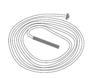
3.1 Device parts checking:
|
|
|
D |
|
H |

|
G |
|
F |

|
C |
|
A
|
|
Object |
Quantity |
Description |
|
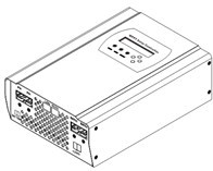
A |
1 unit |
Charge controller |
|
B |
2 pc |
Gallow pulley |
|
C |
4 set |
screw |
|
D |
2 pc |
|
|
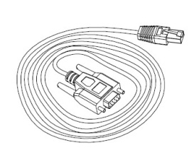
E |
1 pc |
232 turn to RJ45 communication cable |
|
F |
1 pc |
User manual |
|
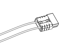
G |
1 pc |
Temperature sensing wire |
|
H |
2 pc |
Fuse wire |
If there is any part missing, please contact your dealer.
3.2 Check for Transport Damage
Check the charge controller for visible external damage, such as cracks in the enclosure. Contact your dealer if you find any damage.
3.3 Identifying the Charge Controller
You can identify the charge controller by the type label. The type label is in the enclosure.
4. Assembly
4.1 Operator:technical personnel;
4.2 Selecting the Mounting Location
|
Danger: Danger to life due to fire or explosion. The charge controller enclosure can become hot during operation. • Do not mount the charge controller on flammable construction material. • Do not mount the charge controller near highly flammable materials. • Do not mount the charge controller in potentially explosive areas. • Do not expose the charge controller to direct sunlight to avoid power loss due to overheating.
|
|
Caution: Danger of burn injuries due to hot enclosure parts. • Mount the charge controller in such a way that it cannot be touched inadvertently during operation.
4.2.1 Dimensions |
L
* W * H:270mm*150mm*88mm
4.2.2 Net Weight
Weight:3kg
• The mounting location and method must be suitable for the weight and dimensions.
• Mount on a solid surface.
• The mounting location must be accessible at all times.
• The charge controller must be easy to remove from the mounting location at any time.
• The ambient temperature should be between -20 °C and +60 °C to guarantee optimal operation.
• Do not expose the charge controller to direct sunlight to avoid power losses due to overheating.
4.2.4 Safety Clearance
Observe the following safety clearance to wall, other devices or objects to ensure sufficient heat dissipation.
|
Direction |
Safety clearance |
|
Sides |
20cm |
|
Top |
30cm |
|
Bottom |
20cm |
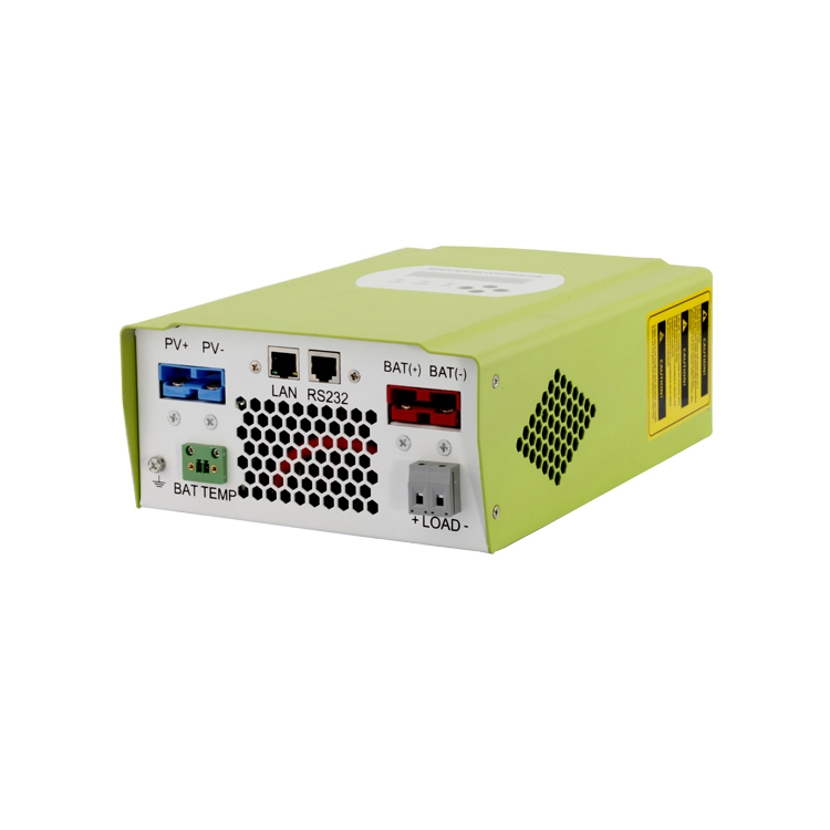
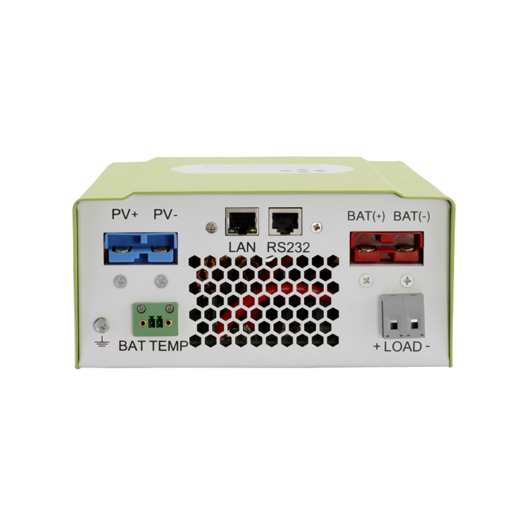
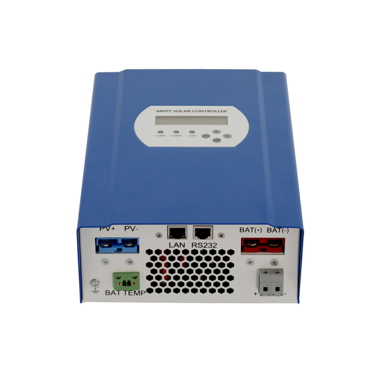
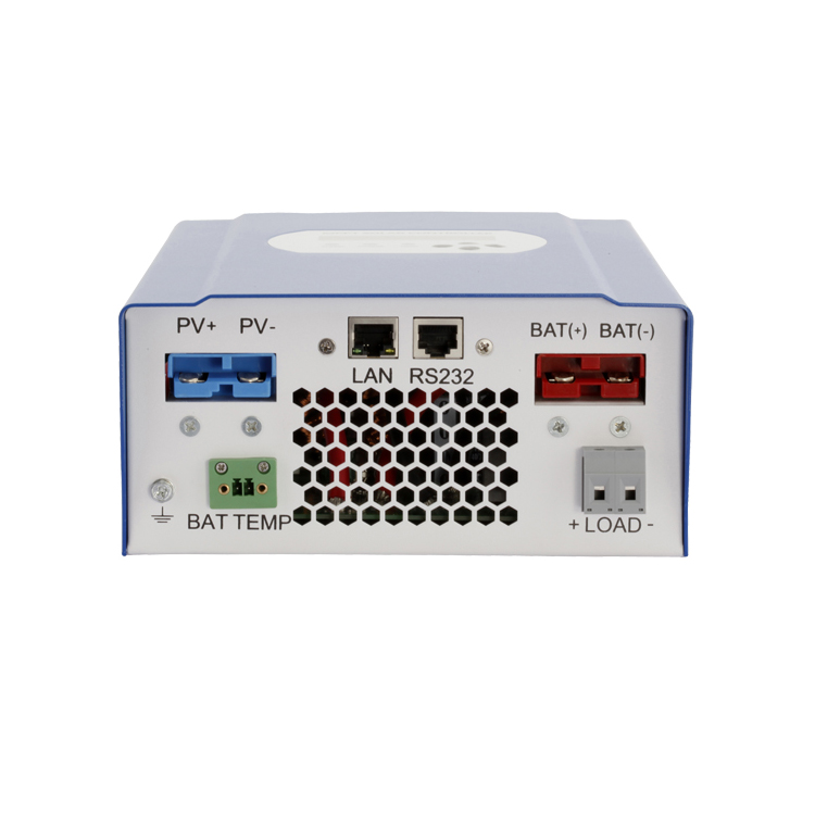
5. Connections of the PV power system
5.2.1 PV String
Solar charge controller device can be connected in series into 1-strings PV modules. Please select PV modules with excellent function and reliable quality. Open-circuit voltage of module arrays connected in series should be less than Max. DC input Voltage (150V); operating voltage should be conformed to MPPT voltage range.
Please use PV cable to connect modules to device. From junction box to device,
voltage drop is about 1-2%. So we suggest the solar charge controller install near PV module, in order to save wire and reduce DC loss.
|
Note: Please don’t connect the PV panel positive or negative to ground.
|
|
Warning: PV module voltage is very high which belongs to dangerous voltage range, please comply with electric safety rules when connecting. |
5.2.2 The voltage
of battery system and types
1) This controller could charge for DC 12 V/ 24 V/48V battery system . It would automatic recognition the voltage system :
2) The controller had already been set to charge 4 types battery as following form . If have other need , the charge parameter also could be reset through machine and solar eagle . The details please check the illustrate .
|
The charging voltage of battery type
|
||||||
|
|
Bulk Voltage |
Floating Voltage |
||||
|
12V |
24V |
48V |
12V |
24V |
48V |
|
|
|
14.2V |
28.6V |
57.2V |
13.2V |
26.4V |
52.80V |
|
|
14.2V |
28.6V |
57.2V |
13.4V |
26.8V |
53.60V |
|
|
14.2V |
28.6V |
57.2V |
13.7V |
27.40V |
54.80V |
|
NiCd |
14.2V |
28.6V |
57.2V |
14.0V |
28.0V |
56.0V |
|
Other |
user-defined(Set by the microcomputer software) |
|||||
|
In the case battery type is not set , use the default battery type (Gel battery). |
||||||
5.2.3 The voltage of DC load system and Max current :
This controller had added DC load output function , the output voltage range based on the type of battery bank system . Like the battery bank voltage is 48V , DC output voltage range will be the range of 48V battery bank working voltage .
1) How to turn DC output turn on/off ?
Please find the DC output control through MPPT or Solar Eagle software . It have 6 way to control it : ON Mode / OFF Mode / Time Control Mode /PV Volt Ctrl / PV&Time Ctrl : Details please check the Setting ;
2) How to set the low voltage protection of DC output ?
This controller have low voltage protection ,the magnitude of low voltage protection
Could be set based on customer’s need . Factory settings is 10.5 V for 1 battery .If the DC output is under the State of providing power for load ,then when the voltage under the magnitude of low voltage protection , the DC output will stop provide power for load . When the voltage of battery is recover to 0.5V bigger the magnitude of low voltage protection ,it will restart . For 48V system , if the DC output under on mode , then when the battery bank will stop provide power under 42V , it will restart when the voltage recover to 42.5 V .
3) Max DC output current
Then Max DC output current is 50A , if the output current out the rated current ,the built-in fuse will be burn . We provide 2 fuse as back up ;
5.2.5 MPPT controller work step
|
Cation : Please follow the steps ,or the machine will be easy to broke . |
Please make sure the MPPT had already been connected in right way .
Step 1 : Open the breaker that connect with battery , make sure the MPPT controller had been connect with with the battery .( When all this done ,the LED and LCD will show some information )
Step 2 :Turn on the breaker that connect with PV module , if the PV module voltage is in the charging range , then machine will start to work .
Step 3 : If need DC load control , please set the DC output control mode , then turn on the DC output breaker .
5.2.6 The step of turn off machine
|
Cation : Please follow the steps ,or the machine will be easy to broke . |
Step 1 : Turn off the PV input breaker ,make sure PV and controller disconnect .
|
Warning:When the controller is charging for battery , please do not turn off the breaker with battery before PV input have not turn off . Or the machine will have unrecoverable fault and this will not in the warranty . |
Step 2: Turn off the battery breaker , the machine will be complete off .
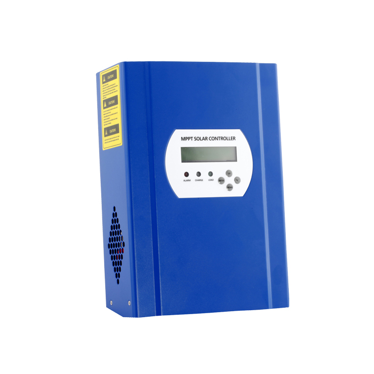
6、Meaning of LED/LCD and function key
6.1 Panel Description
Meaning of LED and function key
ALARM (Red) ----- Alarm Light ( Red , when controller in fault state this light
will on . )
CHANGE(Blue) ----- Charging Light ( Blue ,when controller start to charge power ,this light will on .)
LOAD(Green)------- Load Light (Green , when the DC load turn on ,this load will on )
UP ----------- UP Function Key (For check or page up and numerical increase )
DOWN ------- DOWN Function Key ( For check or page up and numerical reduction )
ENTER ------------------ ENTER key ( For enter in )
ESC ------------------- ESC Key ( For exit and save data )
6.2 Charge Mode
This controller have 3 mode :Constant charging stage ( CC Mode ) , Constant voltage charging stage ( CV Mode ) , Floating charge Stage ( FC Mode ) :
In CC Mode ,the blue light will flash for every second .
In CV Mode ,the blue light will flash for every 3 second .
In CF Mode ,the light will keep on .
( Note : Charging Mode also could check in LCD and solar eagle .)
|
Menu No. |
Menu Type |
Menu Description |
|
1 |
Work Status |
For check the charging state |
|
2 |
Setting |
Parameter set |
|
3 |
Information |
For check the parameter |
6.3.1 The information of LCD display in different menu .
|
SMART 2 MPPT LCD INFORMATION |
Note |
||
|
|
Chg Cur(Charge current) |
If is charging ,it will have information |
|
|
|
Chg Model(Charging Mode) |
Charing Mode |
|
|
|
Time |
Time |
|
|
|
If connect temperature sensing wire ,then will show temperature |
||
|
Work Status |
|
||
|
|
PV Volt(Solar panel voltage) |
PV input voltage |
|
|
|
Chg Power(Real time charge power ) |
Charging power |
|
|
|
Bat Volt(Battery real time voltage) |
Show battery voltage , if is charging , it will show charging voltage . |
|
|
|
|
Will show fault mode under fault state |
|
|
Setting |
Bat Type Sel Setting |
Vented |
Battery type set |
|
Gel |
|
||
|
Nicd |
|
||
|
Sealed |
|
||
|
User Def |
|
||
|
User Bat Set |
Bulk Volt Set |
Special battery ,just need to set Main charging voltage and float charging voltage .Please based on one battery . |
|
|
|
Float |
|
|
|
Max Chg Cur Set |
Could set any data under rated number |
||
|
Date Set |
Date Set |
||
|
Time |
Time Set |
||
|
Gate Address Set |
Gate Address Set |
||
|
Port Set |
Port Set |
||
|
IP Address Set |
IP Address Set |
||
|
Load Control |
Time Control |
Set the double time to control the DC load output on / off |
|
|
|
Load Off Bat Volt |
Set the low voltage protection of battery . ( Based on one battery ) |
|
|
|
On/Off Mode |
Keep on / off state |
|
|
|
PV Volt Ctrl |
Could set the PV voltage to control DC load output turn on/off |
|
|
|
PV & Time Ctrl |
Could set the PV voltage and time to control DC load output turn on/off |
|
|
Information |
Bat Chg SYS |
System Voltage |
|
|
Total power |
Total energy from this machine |
||
|
Firmware Ver. |
Firmware Ver. |
||
|
Machine ID |
Machine ID |
||
|
Bat Type |
Battery Type display |
||
|
IP Address |
IP Address |
||
|
Port |
Port Number |
||
|
Time Load Ctrl |
Last time load control mode |
||
Online Inquiry